VLAN configuration for CCTV is very important to protect the IP cameras against unauthorized access and also to separate the security camera system from other computers and devices that are connected to the IP network.
If you have layer 2 network switches such as Cisco, Netgear, HP, Dell, Dlink and others, they can be easily configured to be used on your CCTV system.

In this article, I will discuss the importance of VLANs for CCTV, how the technology works and how to do VLAN configuration for CCTV projects.
Let's start by learning the VLAN fundamentals, understand how it is used on network switches and learn how to setup VLAN for security cameras.
What are VLANs
VLAN is a technology used to segment networks by creating virtual groups.
It stands for Virtual Local Area Network and it is frequently used on network switches to create virtual groups to allow broadcast traffic control and also to increase the security access level thus avoiding unauthorized access.

On a switch it is possible to create VLANs and associate them to specific switch ports. Devices such as computers and IP cameras that are connected to the same group of ports will be able to communicate in the network.
VLAN traffic segregation
In a scenario with computers and CCTV cameras connected to the same switch it's possible to create VLANs to separate the broadcast traffic.
The diagram below shows an example of a network switch that has IP CCTV cameras and computers connected to its ports. Notice that the VLANs are created and represented by different names, IP address range, and colors.

On IT environment network admins use to name VLANs by using numbers and colors. In the the picture above you can see VLAN 10 and VLAN 20 using the blue and green color respectively to represent different groups.
VLAN Security
VLAN can increase the security in the network by assigning specific switch ports to groups. See the picture below where a man's laptop is connected to port 1 on the Blue VLAN and communicates with PC2 on port 3.
An intruder removes the IP camera from its cable on port 4 to connect his laptop and hack the network. He connects to the Green VLAN to try to hack the security camera but he can't have access to the rest of the network.

The same principle applies to the company worker, he can't have access to the security camera because it's connected to a different VLAN.
How VLAN TAGs work
To be able to control the traffic a switch uses a TAG which is just a way to mark the frames that enter or leave each port,
The frames coming into switch port 1 or 3 are tagged as part of VLAN 10, and frames coming into port 2 or 4 are tagged as part of VLAN 20.
The TAG can be different depending on the switch brand, however there's a universal TAG standard called 802.1Q that is used by most manufacturers.
See the picture below. When the frames come from the IP camera to the switch they are tagged, Those tags are removed before leave the switch.

See below the tags fields according to the universal 802.1Q standard.
SOURCE: Package Source
DESTINATION: Package Destination
TYPE & LEN: Type and size
DATA: The data contained in the package
FRAME CHECK: Frame check
See the illustration of the TAG that is associated with the frame

Communication between switches
When connecting two switches it is necessary to use a special port called "Trunk Port" or "Tagged Port" that will allow the traffic of all the VLANs to pass. So the frames with the 802.1Q TAGs will pass through this port.
Some manufacturers have a slightly difference VLAN ports nomenclature. On Cisco switches documentation the term "Trunk Port" is used for those special ports. Other manufacturers such as Netgear, HP and Dell use the term "Tagged Port" but in any case all of them use 802.1Q TAGs.

Now the IP security cameras and the computers can send traffic from the first to the second switch and still keep the broadcast and security under control.
The first switch can tag the frames that come from the security camera and move them through the trunk (tagged ports) to the second switch.
Type of switches for VLAN configuration
For VLAN configuration is necessary to use layer 2 manageable switches.
Each manufacturer has a different way to create and manage VLANs by using CLI (command line interface) or Web Interface. But in any case the setup is pretty similar and it's very easy to create and configure VLANs.
Example of VLAN configuration for CCTV
Let's take a look at a CCTV camera system with 4 Desktops that use the VLAN 10 and 3 IP cameras and 1 NVR using the VLAN 20.
On this small CCTV project, the VLAN separates the corporate broadcast network traffic from the IP camera broadcast network traffic. See the diagram.

On this CCTV VLAN configuration the desktop users will not be able to have access to the IP cameras or NVR. So your security system is protected.
So, as you can see VLAN configuration for CCTV is very important to keep your system safe from hackers and intruders.
Creating VLANs on a cisco switch
As a quick example, let's see a VLAN configuration on a 8 port Cisco switch. The model is Catalyst 2960 PD that will be configured using the CLI:

USB to serial adapter
The serial cable is a special one used for Cisco Switches and the USB to serial adapter is a TrendNet TU-S9. You can find them on stores such as Amazon.

Trendnet USB to serial adapter

Cisco serial cable adapter
The console port at the left side of the switch will be used to connect a serial cable from a laptop. A CLI will be used to create and configure the VLANs

Laptop using a USB to serial adaptader
A software for CLI commands
After the USB to Serial interface adapter connection is done, you need to setup the software that will be used for the CLI command. I will use a free one called putty. You can download it at https://www.putty.org
Windows serial port configuration
The software configuration is pretty simple, you just need to check which com port the Windows is using for the USB adapter, Just open the Windows Device Manager to check the COM & LPT port. See the picture below.

Windows serial port configuration
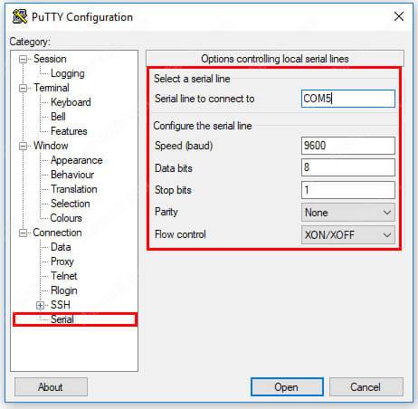
Putty configuration
Putty serial port configuration must match the the data on Windows, for this case they are COM5, Speed 9600, Data bits 8, Stop bits 1 and Parity None.

Putty serial configuration (click to enlarge)

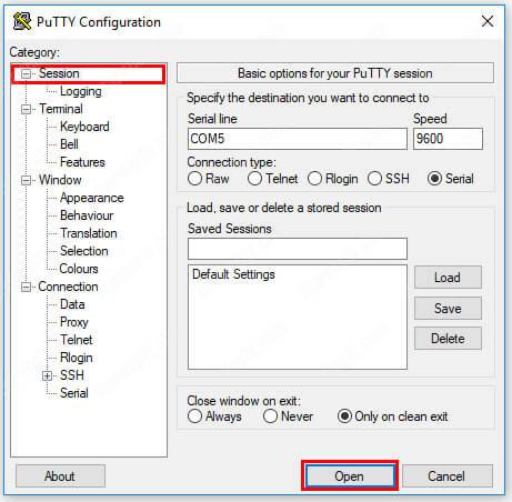
Putty serial connection (click to enlarge)
If the configuration is correct after click "open" you will see the CLI

Putty CLI interface
Create VLAN using the CLI
Create VLANs using a CLI is very simple. In our example I will configure a 8-port Cisco Catalyst 2960 switch. See the steps below:

1. Create the VLAN 10
Open the CLI and execute a sequence of simple commands to get into configuration mode, create the VLAN 10 and give it the name "computers".
Switch#
Switch#conf t
Switch(config)#vlan 10
Switch(config-vlan)#name computers
2. Assign the ports to the VLAN 10
After create the VLAN is time to assign the ports. Get into configuration mode (conf t) select the port range from 1 to 4 and assign them to the VLAN 10.
Switch#
Switch#config t
Switch(config)#interface range fa0/1 - 4
Switch(config-if-range)#switchport access vlan 10
3. Create the VLAN 20
Execute the same sequence of simple commands. Just get into configuration mode, create the VLAN 20 and give it the name "cameras".
Switch#
Switch#conf t
Switch(config)#vlan 20
Switch(config-vlan)#name cameras
4. Assign the ports to the VLAN 20
The VLAN is created, now just make sure the switch is in configuration mode (conf t) select the port range from 5 to 8 and assign the to the VLAN 20.
Switch#
Switch#config t
Switch(config)#interface range fa0/5 - 8
Switch(config-if-range)#switchport access vlan 20
5. Verify if the VLANs were correctly created
Now it's time to check if the VLANs were created and the ports were assigned. Just exit the configuration mode and use the command below:
Switch#(config)#exit
Switch#show vlan
See the picture below with the result. It's possible to see that the VLAN 1o and 20 were created with their correct names and the ports were assigned.

6. Save the configuration
Don't forget to save the configuration you just did. See the command below
Switch#copy running-config startup-config
Creating VLANs on a Netgear switch
Most switches such as Netgear Prosafe Smart allow to configure VLANs by using a Web interface, so the process is pretty simple and fast.
Now will an easy task to create a VLAN configuration for CCTV that works for your project by just using few clicks, it's something really easy to do.
Back to the previous example, let's create the VLAN 10 and VLAN 20 for computers and Security cameras respectively.

Using the browser interface to create VLANs
Create the VLAN configuration for CCTV cameras is very simple, you just need to connect a UTP cable from the laptop to one of switch's port, open a web browser and follow the steps below:
1. Login using your credentials
Check your switch manual to find out what is the default IP address and login password or use the one you just created for your CCTV camera project.

2. Open the TAB to configure VLAN
Open the Switching TAB and click on "VLAN" and note that some VLANs are already created, so don't use the same VLAN ID for your project.

3. Create the VLAN for computers
On the configuration tab just create the ID 10 and give the VLAN a name, in our case that will be "Computers"

5. Set the Untagged ports
Ports that are connected to IP cameras and computers are called Untagged ports, meaning those devices are not bringing Tagged Frames to the ports, so it's necessary to open the Membership TAB and ckeck the ports with an "U"
In our example ports from 1 to 4 must have the " U". See the picture below,

6. Repeat the process for VLAN 20
Create the VLAN, name it and set the untagged ports from 5 to 8


VLAN configuration for large CCTV projects
For larger CCTV projects it's just a question to escalate the network, create VLANs and configure the trunk ports (or tagged ports) between switches.
Just create the VLANs on both switches, use a UTP cable to connected them and configure those ports as trunk or tagged ports. See the diagram.

In this example, the blue computers can't broadcast or have access to the IP cameras or NVRs, so the surveillance network is safe from hackers or virus.
Configuring a Cisco Switch trunk
If you are using Cisco Switches on both ends of the network, just connect the cables to the port, let's say port 10 for example, make sure the switch is using the standard 802.1Q we discussed earlier and convert the port into a trunk.
The configuration is simple, just get into the port you want to use as a trunk and type the commands below:
Switch#config t
Switch#interface fa0/10
Switch(config)#switchport trunk encapsulation dot1q
Switch(config-if-range)#switchport mode trunk
Configuring Netgear Switch tagged ports
As long the switches are connected and the VLANs are created on both sides of the network, you just need to configure the tagged ports on them.
Go to the VLAN Membership and TAG the port you want to connect to the next switch with a " T" that stands for tagged. In our example is the port 10.

Repeat the process for the VLAN 20 by tagging the same port

Conclusion
VLAN configuration for CCTV cameras is not rocket science.
VLAN can be used to secure and improve a CCTV System, it's just a question of switch installation and configuration. It doesn't matter the switch's brand, as long as you have a manageable layer 2 device you can create the VLANs
If you need to use more advanced configuration such as give access to more than one computer to different VLANS than it's necessary to use a router or layer 3 switch for Inter-vlan routing. But this is a topic for another article.
Want to learn more ?
If you want to become a professional CCTV installer or designer, take a look at the material available in the blog. Just click the links below:

Please share this information with your friends...
Great article!! Exactly what I was looking for to help me get this setup. Do you think you’ll make the inter-vlan routing how-to? Would love to see that as well. I had a Cisco connecting to a Netgear on the second floor of my house and I was having problems so I went and got another Cisco 10 port to connect to my main Cisco switch. Thanks again for this.
I was educated with your article. Very easy to understand even without an IT background. Thanks.
thanks you ………………..Claudemir Martins for share knowledge and simplify realy this agood way